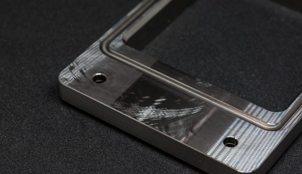
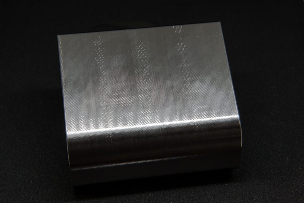
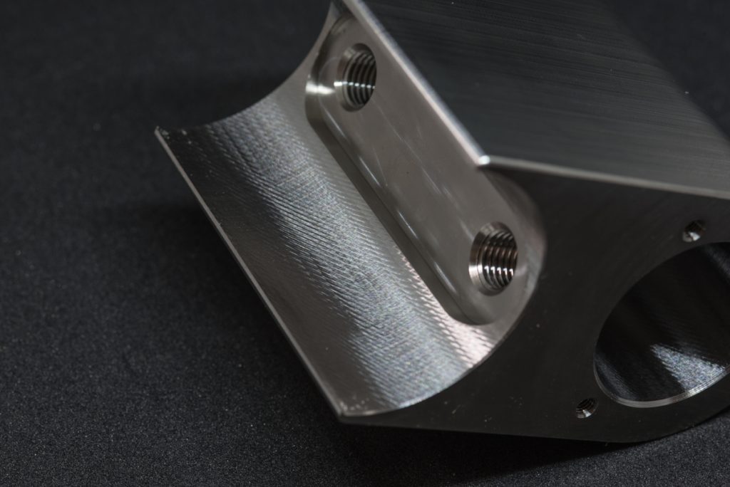
The problem of vibration during CNC machining causes chatter on the surface of the workpiece. It also causes the rework rate and scrap rate are high. The reason for the vibration of the machine tool is generally that the rigidity of the machine tool, the workpiece, and the tool (any one or more) is insufficient. The following describes the aspects of the chatter that need to be investigated and what countermeasures are taken.
The chattering theory analysis is quite difficult in the research of the machine tool. The origin of chattering is quite related to the processing material, mechanical design and cutting conditions. The cutting process involves the material of the workpiece, the hardness, and the size of the feed, etc. And the machine structure involves the structural strength design of each machine tool, such as spindle bearings, turret design, and tool clamping.
Since there are a lot of mathematical equations in the theory, we won’t cover this part in depth. we only divide the chatter situation that the clients often have into the following two categories:
First, Forced Vibration
The forced vibration caused by intermittent cutting or the defective turning of the rotating parts. It generally occurs due to the below reasons:
- The abnormal sound or gear meshing caused by the damage of the bearing
- Poor clamping of the workpiece
- Too large spindle swing
Among such problems, intermittent turning is a problem of machining technique. The most factors of the quality of parts depend on the assembly technique of the machine tool and the quality control of its key components, and also related to the design concept of the machine tool structure. Besides, the vibration characteristics are also directly related to the number of revolutions.
Second, Self-excited Vibration
This is because of the periodic works with unevenness characteristics during the cutting process, and the periodic phases are repetitive overlapping and slightly staggered. It is generally called “resonance”. The main cause comes from the resonance of the natural frequency of the machine tool structure and the frequency of the workpiece clamping system.
Since the natural frequency of the structure is only changed with the adjustment of clamping or fixing mode, changing the cutting conditions (such as changing the rotation speed) can often improve the cutting vibration when the chatter occurs. However, in some occasions where the cutting speed cannot be changed (such as threads tapping), it is only possible to solve such problems by changing the clamping method or even changing the tool or tool fixing method.
Troubleshoot from three aspects: machine, tool, and workpiece:
Machine
- The live center is extended too long;
- The bearing has been damaged and continues to cut.
Tool
- Forming turning with a forming blade
- The angle of the tool is especially the tool cutting edge angle, the clearance angle, the rake angle, etc.
- The sharpness of the blade
- Is the radius of the tool nose arc too large
- Is the cutting parameter suitable?
Workpiece
- The cylindrical turning of slender shafts. If the length-to-diameter ratio (the distance between the cutting point and the clamping point) exceeds 3, it is easy to occur chattering.
- External turning of thin-walled parts.
- Turning of box-shaped parts (such as sheet metal welded structural parts).
- Super hard material cutting.
Comprehensive countermeasures to suppress chattering
There are some more specific and practical methods currently used in the processing:
- Try to choose all the conditions with low cutting resistance, that is, the most appropriate feed rate and cutting speed (or spindle speed).
- Adjust the cutting speed to avoid resonance.
- Reduce the working weight of the part that causes vibration. The smaller the inertia, the better.
- Fix or clamp the place with the highest vibration.
- Increase the rigidity of the machining system, for example by using a tool holder with a high modulus of elasticity, or using a dynamic damper to absorb the impact energy.
- Adjust the direction of the blade and the direction of rotation (depressing the tool while also increasing the stability of the tool).
- Change the shape and advance angle of the tool. The smaller the nose radius of the tool, the better, to reduce the cutting resistance. The Sick Rake Angle must take a positive value to make the cutting direction closer to vertical. The Back Rake Angle is preferably positive, but the chipping ability is relatively poor. Therefore, the slotting knife is generally used to make the inclination angle negative but still has a positive cutting effect.
- The lead angle is as small as possible, preferably zero.
You can find the photo display of the CNC machining parts made by us HERE!